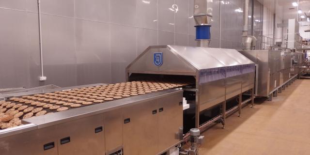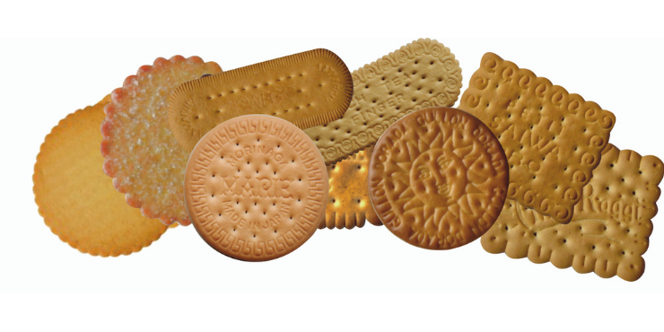
Figure 1/ leading image: Biscuits formed on a cutting machine
Forming a continuous dough sheet and then cutting the dough pieces to the required size and shape and printing the design on the surface of the dough pieces is a traditional and common method of forming the dough for a wide variety of biscuits. These include all semi-sweet biscuits, crackers and hard biscuits.
The process involves feeding the bulk dough to a sheeting line which has typical working widths of 1000mm, 1200mm and 1500mm. The cutting machine line comprises the following machines:
Figure 2: Dingson Food Machinery cutting machine line with 3 roll sheeter, 3 gauge roll units, rotary cutter and panner. Side scrap return to sheeter.
2. Dough sheeting machines
For most applications, a 3 roll sheeter is used. This is designed to produce a continuous, consistent dough sheet with the correct width. The bulk dough is fed directly to the hopper of the sheeter. A grooved forcing roll feeds the dough between a pair of gauge rollers which produce the sheet of dough and lay it onto a conveyor which will carry the dough sheet to the first gauge roll unit.
Scrap dough from the cutter is also fed to the hopper of the sheeter, usually at the back of the hopper so that when sheeted the scrap dough is on the base of the dough sheet.
Figure 3: Diagram of 3 roll sheeter
If you operate in the biscuit industry join our community. Register here!
The gaps between the forcing roll and the top gauge roll and between the two gauge rolls are adjustable. Usually, the forcing roll gap is approximately twice the gauge roll gap.
Figure 4: Back discharge sheeter
An alternative configuration of the sheeter, known as a back discharge sheeter, is often used to feed softer doughs or to feed a vertical laminator.
3. Gauge roll units
Sheeters will produce a dough sheet for semi-sweet biscuits with a thickness usually around 9.0mm. This dough sheet now needs to be reduced to the correct thickness of around 1.3mm for cutting the dough pieces. This reduction is achieved by a series of gauge rolls which reduce the dough thickness step by step. Each reduction is approximately 50%. Typical roll gap settings will be:
Forcing roll gap on sheeter: 18.0 mm
Gauging gap on sheeter: 9.0 mm
1st gauge roll 5.7 mm
2nd gauge roll 2.5 mm
Final gauge roll 1.1 mm (Cutting thickness: 1.3 mm)
Gauge rolls diameters are 420mm – 300mm and are usually constructed from cast iron. They may be of solid construction and may have a bonding of stainless steel on the surface. The object is to ensure the minimum deflection under load to give a very accurate thickness of dough across the width of the dough sheet. Any variation will be evident in the weight and colour of the final baked product.
The gauge roll gaps are adjustable and adjustable scrapers are fitted to top and bottom gauge rolls. The bottom roll will have a slightly faster speed, so that the dough will tend to follow this roll and not adhere to the top roll.
Figure 5: Diagram of dough sheet thickness reduction through the gauge roll unit
Figure 6: Gauge roll units
4. Relaxation conveyor
The process of reducing the dough thickness by a series of gauge rolls stresses the dough structure and this stress must be relieved otherwise the dough pieces will shrink during baking and the result will be misshapen biscuits. The relaxation conveyor, usually 2.0m long, runs more slowly than the delivery of the dough sheet from the final gauge roll unit. The dough sheet will ripple as it feeds on to the relaxation conveyor and as the stress is relieved, the ripples will diminish.
Figure 7: Dough sheet ripples on a relaxation conveyor
5. Dough piece cutting and scrap dough return
The dough sheet is supported on the cutting web as it passes under the cutting rolls. The web may be of woven cotton or a synthetic web. It is important that the dough adheres satisfactorily to the web during the cutting process and does not pick up on the rolls
A rotary cutting machine employs one or two rolls. The two roll machine is prefered for most products as it allows the printing and dockering to be adjusted separately from the cutting of the dough pieces. The pressure of each roll must be accurately adjusted to ensure a clear print of the biscuit design and a clean cut of the dough pieces. The rotary cutter also has a phasing adjustment to ensure that the print is exactly in the centre of the cut dough pieces.
Figure 8: Two roll rotary cutter with print and docker roll and bronze cutting roll. The scrap lattice is lifted and cut and dropped onto the cross scrap conveyor. The cut dough pieces are conveyed towards the panner and the oven
Figure 9: Rotary cutter with separate printing and cutting rolls and scrap dough pick up
Figure 10 Baker Perkins rotary cutter with scrap lift and conveyor
The scrap dough lattice is carried up to cutting discs which cut the lattice into small sections. These are dropped onto a cross conveyor which will deliver the scrap to a return conveyor at the side of the cutting machine. The scrap dough will be returned to the sheeter, where the scrap will be incorporated with the new dough to produce the dough sheet.
5.1 Biscuit cutting and moulding rolls
Printing and cutting rolls are engraved from a bronze roll or more frequently now have plastic inserts mounted on a steel roll. Some snack and cracker products are cut without scrap and baked in a sheet.
Figure 11: Cutter roll with plastic inserts
Figure 12: Scrap-less cutting roll
Cutting rolls and design by Errebi Technology
The design of the inserts is critical to achieve the best final product. The insert design below for Maria is by Errebi Technology.
Figure 13: Maria biscuit
Figure 14: Design for a cutting roll by Errebi Technology
Reciprocating cutters may still be used for products with inclusions such as currants. The cutting head of machines drops vertically onto the dough sheet to print and cut as it follows the motion of the conveyor. It then it rises and returns to print and cut the following rows.
5.2 Scrap dough return to the sheeter
Figure 15: Scrap dough pick up and transfer to a cross conveyor and then to a side scrap return conveyor. The scrap dough is conveyed back to the dough sheeter.
6. Decorating conveyor
The cutting web can deliver the dough pieces onto a separate decorating conveyor, where the surfaces of the dough pieces may be gilded with a liquid egg or milk solution to provide a rich golden gloss to the biscuit. Other materials such as sugar, salt or seeds may be sprinkled on to the dough pieces.
Figure 16: The decorating conveyor follows the cutting web and the scrap lift and cross conveyor. This line has a ‘washover’ unit for applying an egg or milk solution to the dough pieces.
The decorating conveyor delivers the dough pieces to the panner, which lays the dough pieces onto the oven band.
Salt and sugar may be sprinkled onto the dough pieces before baking. This may be done on a decorating conveyor or on the panning conveyor with wire-mesh conveyor band. The wire-mesh band allows surplus salt and sugar to drop through the mesh to a recovery hopper.
Figure 17: Salt / sugar sprinkler mounted over a wire-mesh recovery conveyor from Dingson Food Machinery
7. Panner
The dough pieces are transferred to the oven band by a panner (panning conveyor).
Figure 18: Panning conveyor delivering the dough pieces onto the oven band
It is important that the dough piece pattern fills the oven band evenly and close to the edges of the band. If too much of the oven band is exposed at the edges, it will overheat and cause the colour of the edge biscuits to be darker.
In order to ensure that the dough pieces can be laid close to the band edges, the panning conveyor is mounted on a swivel pivot. Guide wheels are attached at each side at the delivery end nosepiece of the panner and these engage and follow the oven band. As the oven band tracks from side to side, the panner will follow and will lay the dough pieces accurately across the width of the band.
The relative speed of the panner and the oven band will determine the spacing of the rows of dough pieces and this can be adjusted to achieve the optimum spacing.
Figure 19: The panner nosepiece is supported at each side on rollers which allow it to swivel from side to side, following the tracking of the oven band.
8. Control system
Cutting machines are generally controlled by a PLC system with an HMI and touch screen.
Conveyor belts will be automatically tensioned and tracked.
The rolls and conveyors for the complete cutting machine line are driven by AC motors with inverter speed control. These drives operate on a cascade system, usually with the cutting web speed as the master. When the cutting web speed is increased or decreased, the speeds of all the preceding units will follow the increase or decrease to maintain a smooth uninterrupted flow of the dough sheet.
In addition individual speed controls for each unit are used to trim speeds to ensure the optimum flow of the dough sheet through the successive units of the cutting machine.
Roll gap adjustments are made by servo motors with PLC and HMI touch screen control.
Figure 20: Allen Bradley PanelView 800 and PanelView Plus screens from Rockwell Automation
Anybody that can recommend a cutter for crackers for pilot test?
Whole grain laminated biscuit too big in width
Be sure to subscribe to our newsletter by registering so that you do not miss any of our articles and insights.
________________________________________________________________
Reading
Baker Pacific Ltd. www.bakerpacific.com.hk www.bakerpacific.net 2017
Baker Perkins Ltd. www.bakerperkins.com 2017
Noel Almond, Biscuits, Cookies and Crackers, Volume 2. Elsevier Applied Science, 1989
Dingson Food Machinery Ltd. www.dsm-mc.com 2017
Duncan Manley, Biscuit dough piece forming, Manual 3, Woodhead Publishing Ltd. 1998
Laser S.R.L. www.laserbiscuit.com 2017
Reading Bakery Systems. www.readingbakery.com 2017
Spooner Vicars Bakery Systems. www.spoonervicarsbakery.com 2017