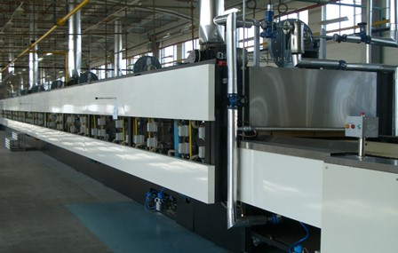
Oven Operation: Direct Gas Fired Oven

Like & comment
Related articles

Continuous Mixing Payback: Faster than You Might Think
Think continuous mixing is too expensive? It actually pays for itself in under two years through labor and energy savings.
Jul 15, 2026
Our experts
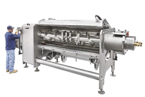
Are Continuous Mixing Misconceptions Holding You Back?
Continuous mixers cut labor and energy, paying for themselves in under two years despite higher upfront costs.
Jul 08, 2026
Our experts

Smart Formulation Of Functional Biscuits Using Artificial Intelligence To Support GLP-1 Modulation
Discover how GLP-1–focused nutrition and AI-driven biscuit formulation are transforming functional bakery products into innovative tools for obesity.
Jul 07, 2026
Our experts
Featured products

Ammeraal Beltech
Dectyl Food Grade synthetic belts: making food production safer!
Available in two versions - a matt finish for non-stick release properties and a glossy variant tailored for high-grip positioning - Dectyl...
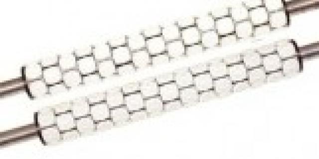
Errebi Technology
Rotary Cutters
The Errebi rollers with interchangeable rings for rotary moulding machines were developed through fine precision work.
They guarantee per...
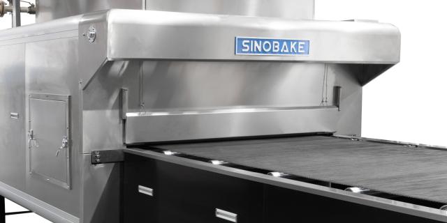
Sinobake Group LTD.
Customized Tunnel Oven: Versatile Baking Solutions for Every Need
Our baking oven incorporates advanced technology to ensure efficient and precise baking. Here are the key technical parameters:Our ovens emp...

Baker Pacific Ltd
Biscuit Baking Technology: Processing and Engineering Manual, Third Edition
Shares over 50 years of experience in the biscuit baking industry world-wide, and is the most updated reference book for senior managers and...
Featured questions


Featured companies

Ammeraal Beltech
Whether it's biscuits, cookies, snacks or other baked items, we have SAFE & CLEAN Bakery Belts for a...
Netherlands

SCHALLER Solutions
SCHALLER, with 36+ years of expertise, delivers turnkey food factories and cost-effective wafer/choc...
Austria

Errebi Technology
Looking for quality moulding equipment? Errebi Technology is a world-famous Italian company making r...
Italy